
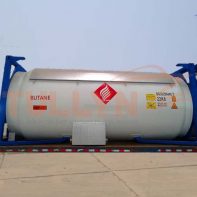
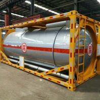
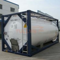
20ft Liquid CO2 T75 cryogenic tank container
20ft Liquid CO2 T75 cryogenic tank container Introduction
The T75 Cryogenic Tank Container is designed to provide a flexible and modal friendly means to transport liquefied CO2,cost-effectively effectively. We offer tanks in a variety of capacity and pressure ratings with or without baffles and or linings. Our tanks comply with IMDG, US-DOT CFR49 – under the exemption, ADR/RID, UIC, TIR, CSC, TC.
Our T75 Cryogenic Tank Container includes zinc lined tanks designed for the transportation of non-refrigerant gases and stainless steel tank containers for pharmaceutical grade propellants.
The medium carried by this T75 Cryogenic tank container covers oxygen, nitrogen, argon, carbon dioxide. Its overall quality achieves domestically level in the field of low-temperatures portable equipment.
20ft Liquid CO2 T75 Cryogenic Tank Container Specification:
| Tank Type | 20’ ISO full-frame collar tank, Type UN Portable Tank T75 With Sunshield, top side rails fitted |
| Frame Dimensions | 20’ x 8’ x 8’6” |
| Capacity | 20,200 Litres +/- 2% |
| M.G.W. | 34,000 kg |
| Tare (est.) | 11,250 kgs +/- 2% with baffle |
| Max Payload | 16,200 kgs |
| MAWP | 18 Bar |
| Test Pressure | 27 Bar |
| Design Temp | -40°C to +55°C |
| Material | Shell & Heads: SA612N; Flanges: SA350LF2 Frame:Q345D or equivalent |
| Shell Thickness | 16mm Nominal |
| Ends Thickness(B.F) | 18mm Nominal |
| Manhole | – One (1) manhole at rear end of the container – DN500 inside diameter, with bolted cover – Spiral wound gasket (PTFE/304) |
| Safety Relief Valve | – One (1) flange for safety relief valve on top of tank (approx 18 offset from vertical center-line. – Size DN80, equipped with Fort Vale relief valve (FV 015/22615F), Fort Vale Bursting Disc, manometer (FV920/20TTBBSPDRY), and custom seals. – Gasket PTFE. |
| Liquid Line | – One (1) flange 2” (DN50) for internal bottom valve and external a manual operated Fort Vale 2” ball valve (FV 802B/0010L) – Internally a dip pipe to the bottom of the tank, with sump in tank-wall – Gasket PTFE/304. – Ball valve provided with blind flange and 3¼” ACME coupling with cap – One (1) purge cock on the ACME coupling. |
| Gas Line | – One (1) flange 2” (DN50) for internal bottom valve and external a manual operated Fort Vale 2” ball valve (FV 802B/0010R) – Internally a standpipe to the gas phase – Gasket PTFE/304. – Ball valve provided with blind flange and 1¾” ACME coupling with cap – One (1) purge cock on the ACME coupling. |
| Manometer | – One (1) ½” connection for pressure gauge, connected to the gas phase of the tank. – External a DN15 ball valve and a ¼’ manometer 0-40 Bar (FV 920/40RBSP) |
| Thermometer | – One (1) ½” connection for the pressure gauge – Thermometer range -40 to +100 ºC and -40 to +212 ºF, dual scale |
| Vessel Design Code | ASME VIII Div. 2 with ASME U2-Stamp |
| Cargo carried | Liquid CO2 |
| Inspection Agency | Lloyds Register or BUREAU |
| Design Approvals | IMDG T50, ADR/RID, CSC, TC, TIR, ISO |
Please note that the above specifications are “general specifications” that pertain to the majority of our products. These specifications should only be used for general, informational purposes. The measurement/size of the goods delivered may be different from the data in the above table, please check with us when order placed.
Reviews
There are no reviews yet.